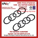
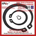

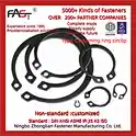
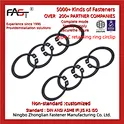
DIN471 External Circlip DIN472 Internal Circlip Marine Shaft Bore Retaining Ring
DIN471 External Circlip and DIN472 Internal Circlip for Marine Shaft and Bore Retention
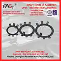
DIN 471 external retaining rings and DIN 472 internal retaining rings, commonly called circlipsorsnap rings, are open-section spring steel fasteners that seat into a precision-machined groove to axially locate bearings, gears, and rotating components on shafts (external) or within bores (internal). We supply DIN 471 shaft circlips and DIN 472 bore circlips in carbon spring steel C67S/C75S per EN 10132-4, as well as A2 (304) and A4 (316) stainless steel, covering shaft and bore diameters from 4 mm to 300 mm. EN 10204 3.1 material certification and third-party inspection are available for marine classification society projects.
What Is a DIN471 / DIN472 Circlip?
Acirclip (circa 19th century from German"Sicherungsring") is a semi-flexible retaining ring with an open gap that allows it to expand or contract during installation. DIN 471 circlips are fitted on the outside of a shaft — the ring is expanded with circlip pliers, slipped over the shaft, and contracts into the shaft groove to form a shoulder that prevents axial displacement of adjacent components. DIN 472 circlips are fitted inside a bore — the ring is compressed, inserted into the bore, and springs outward into the bore groove.
Both types derive their retaining force from the elastic recovery of the spring steel after installation. The ring exerts continuous radial pressure against the groove wall, creating friction and a mechanical shoulder that resists axial thrust loads. This simple, thread-free mechanism makes circlips the preferred retention method in rotating machinery where rapid assembly, disassembly, and maintenance access are required.
In marine engine rooms and machinery spaces, DIN471 shaft circlipsandDIN472 bore circlips are used in centrifugal seawater pumps, bilge pumps, lube oil pumps, electric motor bearing assemblies, reduction gearboxes, steering gear linkages, and winch drives. The vibration, temperature cycling, and salt-laden atmosphere demand correct material selection — carbon spring steel with phosphated finish for protected internal machinery, or stainless steel A4 (316) for exposed and seawater-wetted locations.
DIN471 vs DIN472: Key Differences
| Feature | DIN 471 External Circlip | DIN 472 Internal Circlip |
|---|---|---|
| Installation location | Outside a shaft | Inside a bore / housing |
| Groove location | On shaft outer surface | On bore inner wall |
| Plier action | Tips open (expand ring outward) | Tips close (compress ring inward) |
| Free diameter vs. nominal | Free OD slightly smaller than shaft dia. | Free ID slightly larger than bore dia. |
| Retained force direction | Resists outward axial push from components | Resists inward/outward axial push from components |
| Designation per DIN EN 471-1 | Retaining rings for shafts | Retaining rings for bores |
| International equivalents | BS 3673 Pt.3 / UNI 3654-7436 / D2000 | BS 3673 Pt.4 / UNI 3654-7437 / D1300 |
DIN471 External Circlip Dimensions
Note: Dimensional data per DIN 471. d1 = shaft diameter (nominal), s = ring thickness, G = groove diameter, W = groove width, b = lug width, d3 = free diameter. Supplementary data from RS Pro datasheet.
| d1 (Shaft mm) | s (Thickness mm) | G (Groove dia. mm) | W (Groove width mm) | d3 (Free dia. mm) | b (Lug width mm) | Thrust on groove (N) | Thrust on shaft (N) | Weight (kg/1000 pcs) |
|---|---|---|---|---|---|---|---|---|
| 8 | 0.80 | 7.7 | 0.80 | 8.5 | 2.0 | 3,310 | 3,890 | 0.17 |
| 10 | 1.00 | 9.6 | 1.10 | 10.8 | 2.5 | 4,200 | 6,270 | 0.36 |
| 11 | 1.00 | 10.5 | 1.10 | 11.8 | 2.5 | 5,140 | 7,070 | 0.41 |
| 12 | 1.00 | 11.5 | 1.10 | 13.0 | 2.5 | 5,630 | 7,850 | 0.50 |
| 13 | 1.00 | 12.4 | 1.10 | 14.1 | 2.5 | 6,120 | 8,640 | 0.57 |
| 15 | 1.00 | 14.3 | 1.10 | 16.2 | 3.0 | 7,110 | 10,210 | 0.73 |
| 16 | 1.00 | 15.2 | 1.10 | 17.3 | 3.0 | 7,610 | 11,000 | 0.79 |
| 17 | 1.50 | 16.2 | 1.60 | 18.3 | 3.6 | 10,700 | 12,730 | 1.22 |
| 18 | 1.50 | 17.0 | 1.60 | 19.5 | 3.6 | 11,400 | 13,570 | 1.35 |
| 19 | 1.50 | 18.0 | 1.60 | 20.6 | 3.6 | 12,000 | 14,450 | 1.45 |
| 20 | 1.50 | 19.0 | 1.60 | 21.5 | 4.0 | 12,600 | 15,300 | 1.55 |
| 22 | 1.50 | 21.0 | 1.60 | 23.8 | 4.0 | 14,000 | 17,670 | 1.85 |
| 24 | 1.50 | 23.0 | 1.60 | 25.9 | 4.4 | 15,300 | 20,360 | 2.10 |
| 25 | 1.75 | 23.9 | 1.85 | 26.8 | 4.5 | 20,200 | 22,090 | 2.70 |
| 28 | 1.75 | 26.9 | 1.85 | 30.1 | 4.9 | 22,800 | 25,450 | 3.20 |
| 30 | 1.75 | 28.9 | 1.85 | 32.4 | 5.2 | 24,400 | 27,710 | 3.50 |
| 32 | 1.75 | 30.7 | 1.85 | 34.6 | 5.6 | 25,900 | 30,630 | 4.00 |
| 35 | 1.75 | 33.4 | 1.85 | 37.7 | 6.0 | 28,500 | 34,560 | 4.60 |
| 38 | 1.75 | 36.5 | 1.85 | 41.1 | 6.5 | 31,100 | 39,270 | 5.30 |
| 40 | 2.00 | 37.9 | 2.15 | 43.1 | 7.0 | 37,600 | 43,980 | 6.50 |
| 45 | 2.00 | 42.9 | 2.15 | 48.6 | 7.6 | 42,500 | 51,830 | 8.00 |
| 50 | 2.00 | 47.0 | 2.15 | 54.2 | 8.0 | 47,200 | 58,900 | 9.50 |
| 55 | 2.50 | 52.0 | 2.65 | 59.9 | 8.6 | 64,500 | 73,400 | 14.0 |
| 60 | 2.50 | 57.0 | 2.65 | 65.2 | 9.0 | 69,800 | 83,770 | 16.0 |
| 65 | 2.50 | 62.0 | 2.65 | 70.4 | 9.5 | 75,000 | 94,250 | 18.0 |
| 70 | 2.50 | 67.0 | 2.65 | 75.6 | 10.0 | 80,300 | 105,100 | 20.0 |
| 75 | 2.50 | 72.0 | 3.15 | 80.8 | 11.0 | 85,500 | 116,360 | 23.0 |
| 80 | 3.00 | 76.5 | 3.15 | 86.2 | 12.0 | 102,000 | 128,800 | 30.0 |
Full dimensions for sizes up to d1 = 300 mm available upon request. For sizes above 170 mm, circlips are typically supplied without lugs.
DIN472 Internal Circlip Dimensions (Selected Sizes)
Note: Dimensional data per DIN 472. B = bore diameter (nominal), s = ring thickness, d3 = free diameter, d2 = groove diameter, W = groove width, b = lug width.
| B (Bore mm) | s (Thickness mm) | d2 (Groove dia. mm) | W (Groove width mm) | d3 (Free dia. mm) | b (Lug width mm) | Weight (kg/1000 pcs) |
|---|---|---|---|---|---|---|
| 8 | 0.80 | 8.4 | 0.90 | 7.3 | 2.0 | 0.14 |
| 10 | 1.00 | 10.4 | 1.10 | 9.1 | 2.5 | 0.30 |
| 12 | 1.00 | 12.5 | 1.10 | 11.1 | 2.5 | 0.45 |
| 15 | 1.00 | 15.7 | 1.10 | 14.0 | 3.0 | 0.65 |
| 17 | 1.00 | 17.8 | 1.10 | 16.0 | 3.6 | 0.82 |
| 20 | 1.00 | 21.0 | 1.10 | 19.0 | 4.0 | 1.10 |
| 22 | 1.50 | 23.0 | 1.60 | 20.8 | 4.0 | 1.60 |
| 24 | 1.50 | 25.0 | 1.60 | 22.8 | 4.4 | 1.85 |
| 25 | 1.50 | 26.0 | 1.60 | 23.7 | 4.5 | 1.95 |
| 28 | 1.50 | 29.0 | 1.60 | 26.7 | 4.9 | 2.30 |
| 30 | 1.50 | 31.0 | 1.60 | 28.6 | 5.2 | 2.50 |
| 32 | 1.50 | 33.0 | 1.60 | 30.6 | 5.6 | 2.80 |
| 35 | 1.50 | 36.0 | 1.60 | 33.5 | 6.0 | 3.20 |
| 40 | 1.75 | 41.5 | 1.90 | 38.5 | 7.0 | 4.50 |
| 42 | 1.75 | 43.5 | 1.90 | 40.5 | 7.0 | 4.90 |
| 45 | 1.75 | 46.5 | 1.90 | 43.5 | 7.5 | 5.40 |
| 47 | 1.75 | 48.5 | 1.90 | 45.5 | 7.5 | 5.70 |
| 50 | 2.00 | 51.5 | 2.20 | 48.0 | 8.0 | 7.00 |
| 55 | 2.00 | 56.5 | 2.20 | 53.0 | 8.5 | 8.00 |
| 60 | 2.00 | 61.5 | 2.20 | 58.0 | 9.0 | 9.00 |
| 62 | 2.00 | 63.5 | 2.20 | 60.0 | 9.0 | 9.50 |
| 65 | 2.50 | 68.0 | 2.75 | 62.5 | 9.5 | 14.0 |
| 70 | 2.50 | 73.0 | 2.75 | 67.5 | 10.0 | 16.0 |
Full dimensions for bore sizes up to 300 mm available upon request. For sizes above 170 mm, circlips are typically supplied without lugs.
Materials and Surface Treatment
| Material | Grade / Standard | Carbon Content | Hardness (HRC) | Surface Finish | Application Environment |
|---|---|---|---|---|---|
| Carbon spring steel | C67S per EN 10132-4 | 0.65 - 0.73% | 44 - 52 | Phosphated and oiled | Internal machinery, protected locations, dry environments |
| Carbon spring steel (alt.) | C75S per EN 10132-4 | 0.70 - 0.80% | 46 - 54 | Phosphated and oiled | Higher spring force required; same environment limits as C67S |
| Austenitic stainless A2 | SS 304 / X5CrNi18-10 | max. 0.07% | HRC 25 - 32 (cold worked) | Passivated | General marine, moderate corrosion exposure |
| Austenitic stainless A4 | SS 316 / X5CrNiMo17-12-2 | max. 0.07% | HRC 25 - 32 (cold worked) | Passivated | Seawater-wetted, splash zone, high chloride environments |
| Martensitic stainless | SS 420 / 2Cr13 | 0.16 - 0.25% | HRC 44 - 50 (heat treated) | Heat treatment coloring / passivated | Corrosion resistance required with spring-level hardness |
Material selection guidance: C67S is the standard and most cost-effective material for circlips per DIN 471/472, providing excellent elastic recovery after heat treatment to HRC 44-52. However, carbon spring steel requires surface protection (phosphating and oiling) and is suitable only for protected internal machinery environments. For any marine location with moisture, salt spray, or seawater exposure, stainless steel circlips are essential. A4 (316) is recommended for direct seawater contact; A2 (304) suits enclosed engine room environments where humidity is present but direct water contact is limited. SS 420 offers a middle ground: martensitic hardness comparable to C67S with moderate corrosion resistance.
Marine Applications
Note: Application examples based on typical industry practice for marine machinery assemblies.
| Assembly | Circlip Type | Function | Typical Size Range | Recommended Material |
|---|---|---|---|---|
| Centrifugal seawater pump | DIN471 (shaft) + DIN472 (bore) | Impeller axial retention, bearing positioning | d1 20 - 45 mm | A4 (316) stainless |
| Electric motor bearing assembly | DIN471 (shaft) + DIN472 (housing) | Bearing outer race and inner race axial location | d1 25 - 65 mm | C67S (enclosed) / A2 (exposed) |
| Reduction gearbox | DIN471 (shafts) + DIN472 (bearing bores) | Gear and bearing axial retention on multiple shafts | d1 15 - 80 mm | C67S (oil bath environment) |
| Bilge pump | DIN471 (motor shaft) | Impeller retention on shaft | d1 10 - 25 mm | A4 (316) stainless |
| Steering gear linkage | DIN471 (pin/shaft) | Clevis pin and yoke retention | d1 12 - 30 mm | A4 (316) stainless |
| Winch drive assembly | DIN471 + DIN472 | Drum bearing and gear axial location | d1 25 - 60 mm | C67S (grease-lubricated) / A2 |
Installation and Failure Prevention
Correct installation is critical for circlip performance in marine machinery. The following points address the most common installation errors and failure modes:
| Issue | Cause | Consequence | Prevention |
|---|---|---|---|
| Over-expansion | Circlip stretched beyond its elastic limit during installation | Permanent deformation; ring does not contract fully into groove; loose fit and axial play | Use correct plier size per DIN 475; expand only to clear the shaft, not beyond |
| Incorrect groove tolerance | Groove diameter out of DIN 471/472 tolerance | Too large: ring sits loosely, inadequate thrust resistance. Too small: ring cannot seat, high installation stress | Verify groove dimensions per DIN tables before installation |
| Corrosion failure | Carbon steel circlip in wet or saltwater environment | Rust, pitting, section loss; ring fractures under load | Specify A4 (316) stainless for any seawater-wetted or splash zone location |
| Fatigue cracking | Cyclic vibration and pressure pulses in pump/gearbox assemblies | Crack initiation at the gap (stress concentration point); ring breaks open | Ensure correct material hardness; consider heavy-type (thicker section) for high-vibration assemblies |
| Wrong type installed | External circlip fitted in bore or vice versa | Ring cannot seat in groove; zero retention; component dislodges | DIN471 = shaft (external), DIN472 = bore (internal); verify before installation |
Why Choose sinofastener for DIN471 / DIN472 Circlips?
- Full size range coverage: DIN471 external and DIN472 internal circlips from 4 mm to 300 mm shaft/bore diameter, covering the majority of marine pump, motor, and gearbox assemblies.
- Material flexibility: Carbon spring steel C67S/C75S per EN 10132-4 for standard applications; A2 (304), A4 (316), and SS 420 stainless steel for corrosion-critical marine locations.
- Quality assurance: Dimensional inspection on every batch; EN 10204 3.1 material certification available; third-party inspection accepted for marine classification society projects.
- 50,000 tonnes annual capacity: High-volume production capability ensures competitive pricing and reliable delivery for fleet maintenance programs and newbuild projects.
Standards Reference
- DIN 471 (now DIN EN 471-1) — Retaining rings for shafts
- DIN 472 (now DIN EN 472-1) — Retaining rings for bores
- EN 10132-4 — Cold rolled steel strip with high carbon content for spring steel, temper rolled and quenched and tempered delivery conditions
- DIN 475 — Circlip assembling tools (pliers)
- BS 3673 Part 3 — External circlips (British equivalent)
- BS 3673 Part 4 — Internal circlips (British equivalent)
- UNI 3654-7436 — External circlips (Italian equivalent)
- UNI 3654-7437 — Internal circlips (Italian equivalent)
- EN 10204 3.1 — Inspection certificate with specific test values
FAQ
Q1: What is the difference between DIN 471 and DIN 472 circlips?
DIN 471 circlips are external retaining rings installed on the outside of a shaft to prevent axial movement of components such as bearings and gears. DIN 472 circlips are internal retaining rings installed inside a bore or housing. The two types differ in geometry, installation direction, and plier action — DIN 471 requires expanding the ring, while DIN 472 requires compressing it.
Q2: Why use stainless steel circlips instead of carbon spring steel in marine applications?
Carbon spring steel circlips (C67S) are the standard material per DIN 471/472 and offer excellent spring properties at HRC 44-52. However, they require phosphated and oiled surface protection and will corrode rapidly in wet or saltwater environments. For any marine location exposed to moisture, salt spray, or seawater contact, austenitic stainless steel circlips in A2 (304) or A4 (316) are essential. A4 (316) provides the highest corrosion resistance in chloride-rich environments.
Q3: What does"DIN EN 471-1"mean — is it different from DIN 471?
DIN 471 has been redesignated as DIN EN 471-1 following European standard harmonization. The dimensional specifications, tolerances, and material requirements remain the same. Circlips manufactured to DIN EN 471-1 are dimensionally identical to those made to the older DIN 471 designation. The same applies to DIN 472, now designated DIN EN 472-1.
Q4: How do I determine the correct circlip size for my application?
The circlip size is determined by the shaft diameter (for DIN 471) or bore diameter (for DIN 472). Select the circlip with a nominal size matching the shaft or bore. The groove diameter and width must be machined to the tolerances specified in the DIN 471/472 tables. Verify both the thrust load requirement (axial force the circlip must resist) and the available radial space. For high-load applications, consider the heavy-type variant with increased thickness.
Contact Us
Email: sales@sinofastener.com
Website: www.zlfastener.com | www.sinofastener.com (Main)